Symmetricom SA.22c Tricks
Published on
So a while back I got a few of these Symmetricom SA.22c rubidium clocks off eBay:
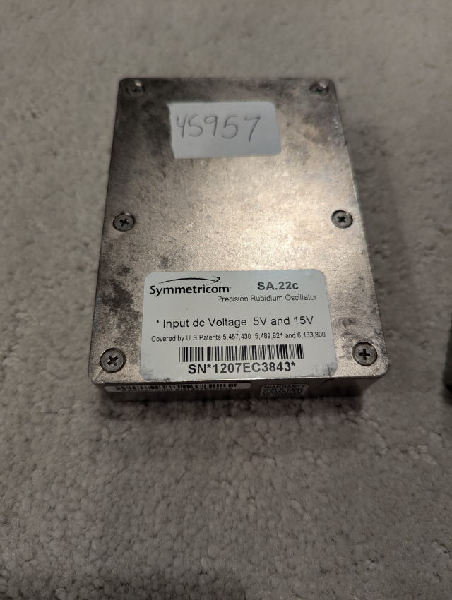
Somehow I only ordered one, but the seller sent me 3. I’m not complaining though - one can never have too many clocks. It’s been a very long time of on and off tinkering with these (including a custom PCB I totally didn’t forget to do a ground pour on - oops) and I finally got them to work and wanted to share some of the info I couldn’t find on the internet about these.
At a super basic level, all you need to do is feed it +15v and +5v, and it will do its thing. Serial is available at 57.6k baud TTL. Their interface is kind of wonky, and I’ll get into that a bit later. Besides serial, you have a PPS in and out, reference frequency out, and analog correction in.
First let’s look at the reference frequency. It seems all of my units came out of old cell sites, since they were all set to 15MHz. Changing these to 10MHz was an easy fix, however requies some understanding of how the unit operates. Very basically, they have a 60MHz base clock that is then manipulated to get different output pulses/reference signals. The main reference frequency output is a divider from the Once you have a connection to the unit, type “o” and then the power of 2 you want to divide the base crystal by. E.g.:
| “o” value | Resultant Frequency | Division |
|---|---|---|
| 0 | 60MHz | 0 |
| 1 | 30MHz | 2 |
| 2 | 15MHz | 4 |
| 3 | 10MHz | 6 |
Once I sent the “o3” command, the unit switched to a 10MHz output signal. Nice!
Next let’s look at the config registers. This is necessary in order to enable 1PPS output from your unit (mine was disabled). I pulled these values out of a manual, however the bit ordering they claim is incorrect (as of the 6.02c firmware on my unit; it could have changed later though I doubt it given the register values I have match example ones in the manual). Per their manual:
r>p
Control Reg: 204C

Note: For the above example, C corresponds to bits 12-15, 4 corresponds to bits 8-11, 0 corresponds to
bits 4-7, and 2 corresponds to bits 0-3 in the following table.
However per my own testing I noticed this to be inverse - i.e. bit 0 is the rightmost bit - so in the case of the given example, bits 0-3 actually correspond to C, and NOT 2 as mentioned.
Let’s take the register of 004C from my unit as an example, and decode it:
| Bit | Hex Value | Value | User Settable? |
|---|---|---|---|
| 0 | 1 | 0 = Lamp Switch Off (default); 1 = Lamp Switch On | No |
| 1 | 2 | 0 = Unit is locked; 1 = Unit is unlocked | No |
| 2 | 4 | 0 = Enables FXO Output; 1 = Disables FXO Output | Yes |
| 3 | 8 | 0 = Enables PPS Output; 1 = Disables PPS Output | Yes |
| 4 | 1 | 0 = Enables ACMOS Output; 1 = Disables ACMOS Output | Yes |
| 5 | 2 | 0 = Low C-field; 1 = High C-field | Probably?* |
| 6 | 4 | 0 = Enables sine output to 40% amplitude; 1 = Disables 40% | Yes |
| 7 | 8 | 0 = No addt’l level; 1 = +15% Max Output | Probably?* |
| 8 | 1 | 0 = No addt’l level; 1 = +10% Max Output | Probably?* |
| 9 | 2 | 0 = No addt’l level; 1 = +5% Max Output | Probably?* |
| 10 | 4 | 0 = Unit is OK; 1 = Unit requires service | No |
| 11 | 8 | 0 = No 1PPS Sync; 1 = 1PPS Locked | No |
| 12 | 1 | 0 = No external 1PPS Signal; 1 = Ext. 1PPS Detected | No |
| 13 | 2 | 0 = Frequency Control disabled; 1 = Freq. Ctrl. enabled | No (set via another command) |
| 14 | 4 | Reserved | No |
| 15 | 8 | Reserved | No |
*: Manual claims “Not configurable in customer firmware”; however it also says the control register can be set “during TACO”. I have no idea what TACO is; the manual does not say - but I hope it’s yummy!
So, in my case, register 004C corresponds to disabled FXO and PPS, enabled ACMOS, the unit not requiring service, and no external PPS signal detected or synced. I had to change this to 0044 (removing bit 3) to enable the PPS output.
After this, you have to save the settings. You do this with the t command. However you must tickle it in a very specific way to get it to save. According to the manual (and what I’ve done) you must enter in this number in order to get it to save (and it doesn’t even show up when you type it):
r>t
5987717       <-- I added this; you don't even see it in the command output
Tuning Data saved
r>
After this, the oscillator can be rebooted, and the saved settings will persist.
Lastly, I thought this was a bit funny, but I actually ended up powering this oscillator off USB-C for the time being. Coincidentally, the clock wants a 15VDC input, and guess what has 15 volts as a power profile? My USB-C charger! I had a spare trigger cable laying around, so I used that to power it until I can get a proper power brick.
This was certainly confusing and a bit of a whirlwind to figure out. If someone has any tips or tricks about these please feel free to contact me! I plan on updating this page from time to time as a living document.