Quad Serial PPPS Hat
Published on
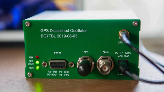
A while back I got a pair of these BG7TBL GPSDO clocks off ebay:
If you recall the release of the Raspberry Pi CM4, you may remember the onboard network controller has a neat feature up its sleeve: IEEE1588 aka Precision Time Protocol support. The regular Pi 5 followed in the footsteps of the CM4 and also has PTP support. Immediately I wanted to make a PTP server for kicks and giggles since I am a giant time nerd. I did some initial testing with a horrible amalgamation of a screw terminal RS-232 to TTL level shifter and a cut up RJ45 cable and some breadboard jumpers. I am so ashamed, there will not be a picture attached here. Despite the horrible cabling, it did in fact work - after some software setup, a /dev/pps0 device appeared and was reporting ticks via ppstest. This post is not really meant to go over the intracacies of setting up a time server (especially a PTP one) but rather the custom hardware I whipped up to solve the shoddy wiring.
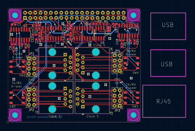
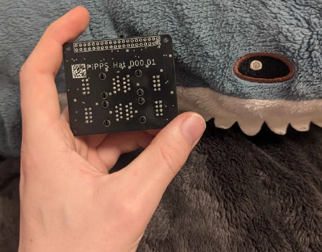
Initially, I was just going to put a single RJ45 and associated level shifters on the board, but ended up with a few more goodies. First, I bumped the port count to 4, utilizing UARTs uart0, uart2, uart3, and uart4 (apparently uart1 is the host console on the Pi5, and not for peripherals). As you can see fitting it all was quite tight and pretty much perfect. I tracked the board, and send it to the PCB house to get printed. I don’t want to name them, but the PCB house I use has a new thing where you can get your boards serialized with a unique datamatrix code. I hadn’t tried it out before, and it was sort of a surprise to me, but it ended up well enough. I definitely like it, but next time I would definitely plan out a bit better where the code goes.
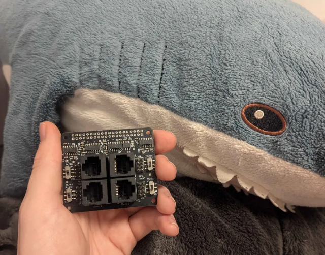
Additionally, I added a couple quality of life features: selectable null-modem crossover and PPS pin selection. The selectable crossover is huge, since you don’t have to make custom cables for a downstream device - if you can get it into a Cisco-pinned RJ45 plug, you can get data in and out. No matter if your connected device is DTE or DCE you can get it connected. This is handled by a switch next to the port, and the PPS pin select is handled by a small jumper next to the port. This allows you to pick which pin is driving the PPS signal, again without having to make a custom cable. Honestly, I added these because I was lazy, and didn’t want to figure out which way the clock was; but this actually ended up benefitting me more since it adds a ton of flexibility. And, as per the pHAT spec, there is an EEPROM, but I need to make a dtoverlay and push it upstream for the EEPROM to really do anything. The final board came out pretty nice though, and worked the first time, which was a welcome surprise. Shark even approves:
Getting the serial lines to work on the Pi requires a simple addition to the config.txt file on the SD card, along with the pps-gpio overlay which adds a driver for a PPS-via-GPIO device on pin 18:
[all]
enable_uart=1
dtoverlay=uart0
dtoverlay=uart2
dtoverlay=uart3
dtoverlay=uart4
dtoverlay=pps-gpio,gpiopin=18
Currently, I have this in use at home running one of the BG7TBL clocks into the Pi for a local NTP server, plus out-of-band serial access to my router and two switches. I used ser2net for the serial console server bit, and it works a treat. I need to tinker with it a bit to make it work better in my workflow, but it works well enough now. Which is part of the point, this isn’t just a time-keeping hat, it’s also an easy to use serial console hat where you don’t need crossover cables to plug into different devices. And what would a post about time be without an error measurement:
natalie@time:~ $ chronyc sources -v

  .-- Source mode  '^' = server, '=' = peer, '#' = local clock.
 / .- Source state '*' = current best, '+' = combined, '-' = not combined,
| /             'x' = may be in error, '~' = too variable, '?' = unusable.
||                                                 .- xxxx [ yyyy ] +/- zzzz
||      Reachability register (octal) -.           |  xxxx = adjusted offset,
||      Log2(Polling interval) --.      |          |  yyyy = measured offset,
||                                \     |          |  zzzz = estimated error.
||                                 |    |           \
MS Name/IP address         Stratum Poll Reach LastRx Last sample
===============================================================================
#x NMEA                          0   4   377    19   +474ms[ +474ms] +/-  175ms
#* PPS                           0   4   377    17   -126ns[ +504ns] +/-  181ns
^- time-a-b.nist.gov             1  10   377   738  -2680us[-2673us] +/-   16ms
^- time-d-b.nist.gov             1  10   377   295  -2623us[-2619us] +/-   16ms
^- india.colorado.edu            1  10   377   526  +1939us[+1944us] +/-   11ms
natalie@time:~ $
Hundreds of ns isn’t all that bad for the realistically low accuracy I need at home.
Overall, I am very happy with how this turned out. I still have a dozen or so from the run, and if you are interested in one please email (see the home page) or otherwise get in contact and we can chat. I think if I were to do it again I would probably add some sort of digital mux chip so that the Pi could control the crossover function without user input, and making a smaller connector for the serial ports with some sort of intermediate [unnamed connector] -> RJ45 adapter to add more space on the board. That said I am still extremely happy with this design, and it was a good exercise in quickly turning around a PCB.